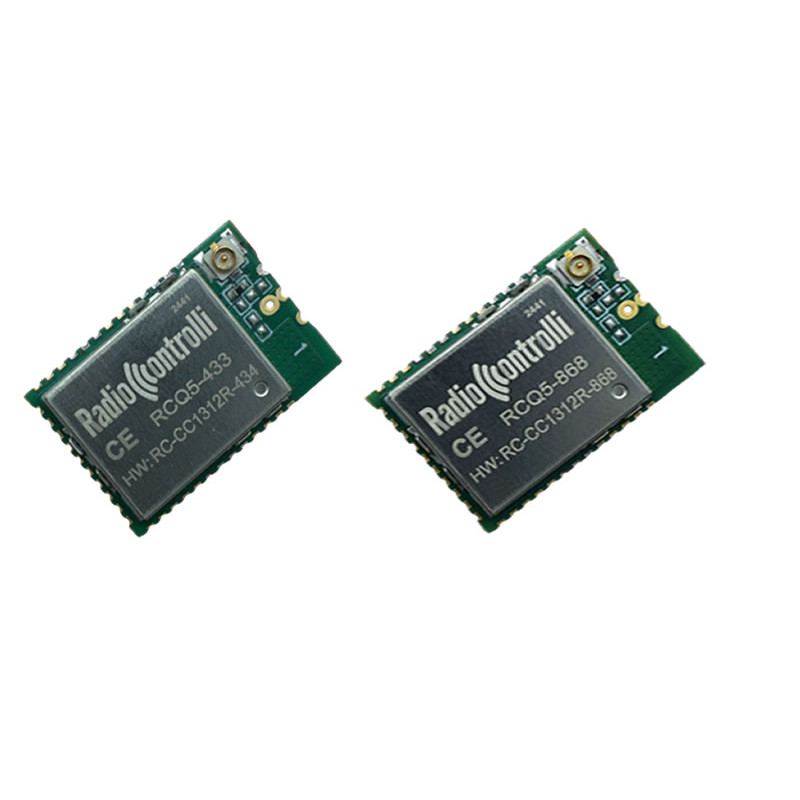
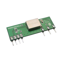
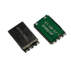
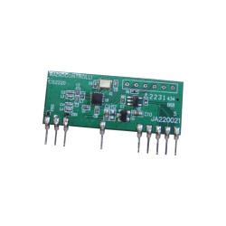
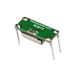
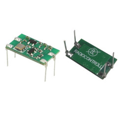
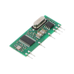
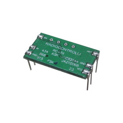
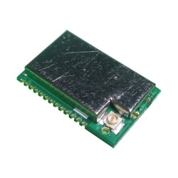
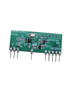
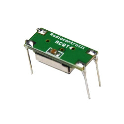
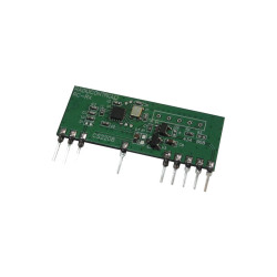
RCQ5-433 Radio modem multifunction 433MHz
RCQ5-433 433MHz Multichannels Radio Modem
The RCQ5 module is a module with multiple features:
- It is a wireless radio modem with AT commands, providing an RS232 wireless link with an RF data rate of up to 200 kbps (modulation 2-GFSK).
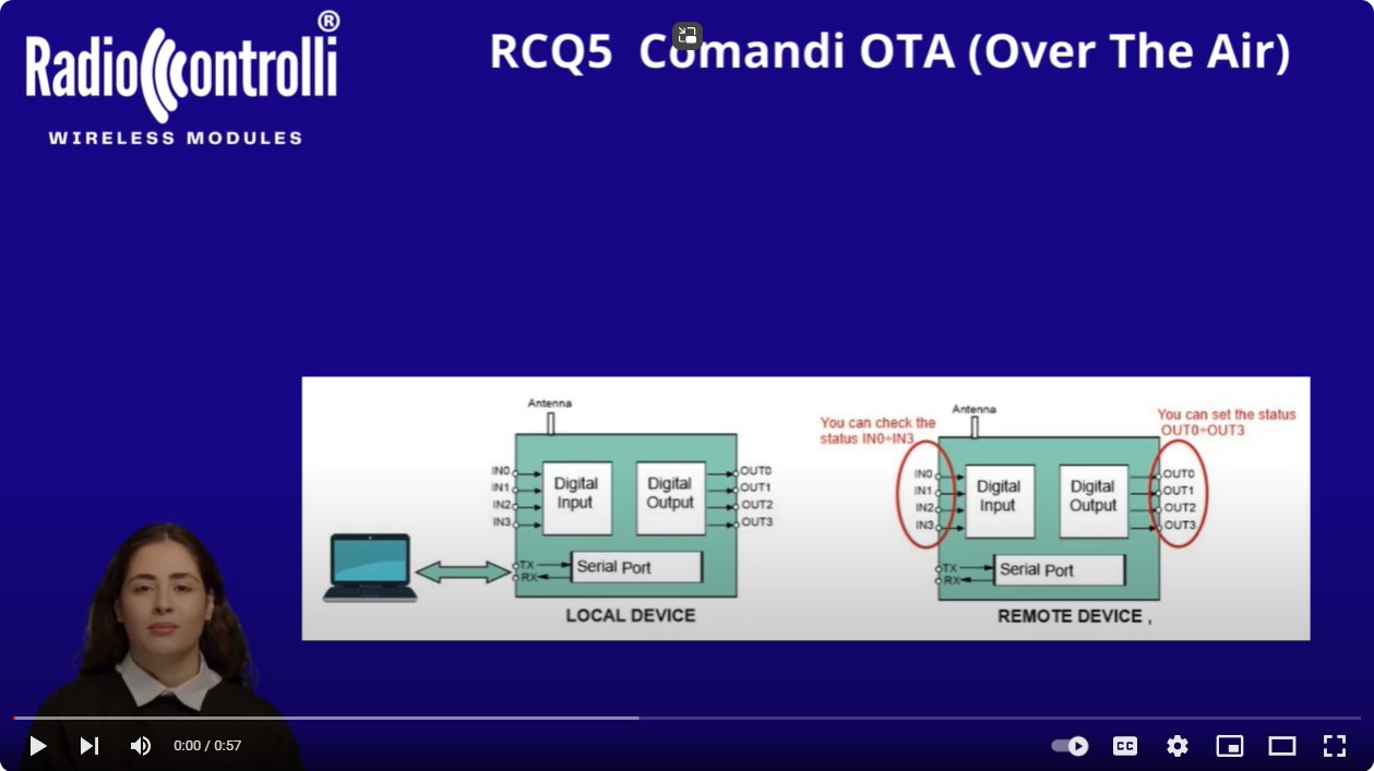
- The module has the ability to manage 4 digital outputs and 4 digital inputs both locally and remotely (OTA Over The Air Command) via sending simple AT command.
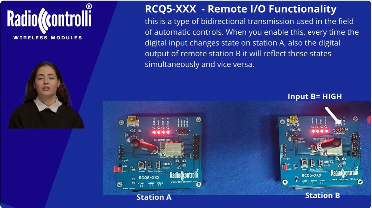
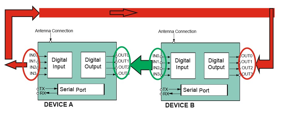
- Remote I/O functionality, this is a type of transmission bidirectional used in the field of automatic controls. When you enable this, every time the digital input changes state on station A, also the digital output of remote station B it will reflect these states simultaneously and vice versa.
433MHz Multichannel Radio Modem
The functionalities of the device RCQ5-433 are the following :
- Radio Modem with AT Command (Transparent Transmission Protocol)
The RF modem is very simple to use and provides a wireless RS232 link with a RF data rate of up to 200kbps (2-GFSK modulation).
The module can work also in Long Range Mode (LRM) with a RF data rate egual to 2.5kbps.
The transceivers has the functions of a complete radio modem and simply require CMOS/TTL data at the transmit input and the corresponding transceiver(s) output
the same data. Preamble and CRC are automatically generated and added to the RF transmission.

- Over The Air Command (OTA Command)
The module has the ability to manage No. 4 digital outputs and No. 4 digital inputs both locally and remotely (OTA Command) by sending simple AT commands.

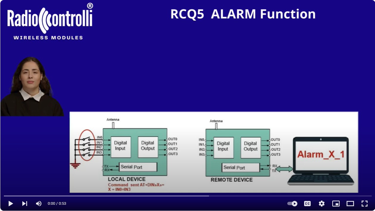
- ALARM Functionality
With this function, when a digital input change status (DEVICE A) a message will be transmitted via UART to the DEVICE B : “Alarm_0_1

- Remote I/O Functionality
This is two-way transmission used in the field automatic control. It is possible Turn ON and turn OFF the remote IO mirroring function.
When we enable the Remote I/O function, if any Digital Input is change on the Station A, the digital output of the remote Station B will also mirror these states at the same time.
| Technical Characteristics | MIN | TYP | MAX | UNIT |
| Supply Voltage | 1.8 | 3.0 | 3.60 | Volt |
| Supply Current (RX mode) | 5.8 | mA | ||
| Supply Current (TX mode / +10dBm) | 13.4 | mA | ||
| Supply Current (TX mode / +14dBm) | 24.9 | mA | ||
| Supply current sleep mode | 2 | µA | ||
| Frequency Range CEPT/ERC/REC 70-03 | 913 | 917 | MHz | |
| RF Output Power | -10 | +14 | dBm | |
| RF Sensitivity (50 Kb/sec Data Rate) |
-110 | dBm | ||
| RF Sensitivity (2.50 Kb/sec Data Rate) |
-118 | dBm | ||
| Operating Temperature range | -20 | +70 | °C | |
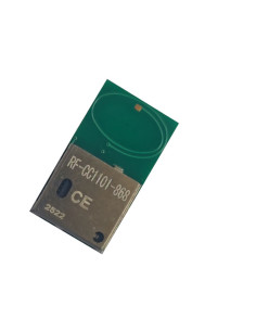
| Mechanical Dimensions 15 x 22mm |

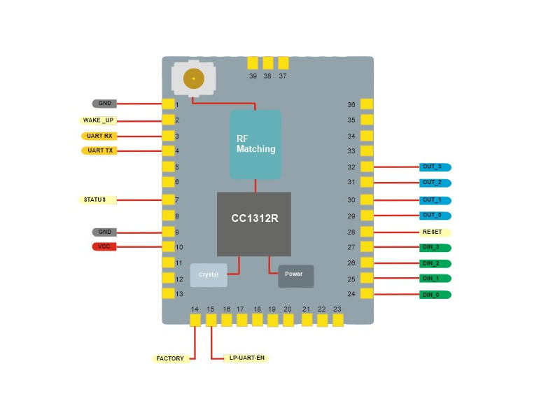
| Pads | Name | Description |
| 1,9,37,39 | GND | Ground |
| 2 | Wake-Up | Wake Up from Sleep mode (Low Active) |
| 3 | RX | UART RX |
| 4 | TX | UART TX |
| 7 | STATUS |
When the system operates normally is HIGH When the system is in Sleep mode is LOW When will use Factory Reset this will flash |
| 10 | VDD | 1.8Volt ÷ 3.8Volt main chip supply |
| 14 | FACTORY |
- Factory Reset Low Active After pull down this pin, and then powering ON again the pin 7 (STATUS) will flash 5 times and then stay on, means that the factory reset has been restored. |
| 15 | LP-UART | LP-UART enable low active |
| 24 | DIN-0 | Digital Input DIN-0 |
| 25 | DIN-1 | Digital Input DIN-1 |
| 26 | DIN-2 | Digital Input DIN-2 |
| 27 | DIN-3 | Digital Input DIN-3 |
| 28 | RTS | RESET (Active Low internal pullup) |
| 29 | OUT-0 | Digital Output OUT-0 |
| 30 | OUT-1 | Digital Output OUT-1 |
| 31 | OUT-2 | Digital Output OUT-2 |
| 32 | OUT-3 | Digital Output OUT-3 |
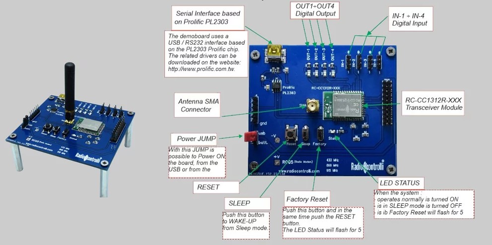
The Evaluation KIT
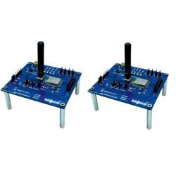
N. 2 Evaluation Board with SMA Antenna
N. 2 USB Cables
- Frequency
- 322MHz
- Modulation
- 2_GFSK
- Supply Voltage
- 3.0 - 3.6 Volt
- Consumption
- 5.8/24mA
- Dimension
- 22 x 15.0mm
- RF Power Output
- +14dBm
- Sensitivity
- -118dBm

